How To Set Scale In Autocad Layout
Printing a drawing at a specific scale
AutoCAD typically deals in millimetres, but Ordnance Survey data available in Digimap is provided in metres. The instructions below explain how to re-calibration a drawing from metres to millimetres.
Set the correct map units
- Open the DWG file downloaded from Digimap in AutoCAD.
- Type 'units' in to the command bar and printing enter, the Drawing Units window appears:

- Using the dropdown in the 'Insertion Scale' department select 'Meters' if not currently fix.
- Press the OK button to close the window.
Change the model file from metres to millimetres
AutoCAD now knows that each unit of measurement in the map is 1 metre in the model. However, printing in AutoCAD is based on ISO paper sizes using millimetres and so in lodge to impress at a specific scale you need to catechumen the model from metres to millimetres.
- Press Ctrl + A on your keyboard to select all elements in the drawing.
- Blazon 'calibration' in to the control bar and press enter.
- AutoCAD will inquire 'SCALE Specify base point:', blazon '0,0' (without the quotes) and press enter.
- AutoCAD will inquire 'SCALE Specify scale factor or [Copy Reference]', blazon '1000' (without the quotes) and press enter. You lot may need to printing the zoom extents button
 to view the data.
This will accept changed the drawing from metres to millimetres.
Creating a impress file at a specified scale
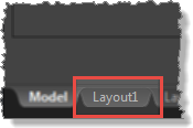
- In the main AutoCAD map window select the 'Layout1' tab at the bottom left.
- On the layout page, delete the existing Viewport to give you a bare folio. Do this by clicking one time on the black box that highlights the extents of the Viewport (it will change to blue to indicate that it is selected), then press delete.
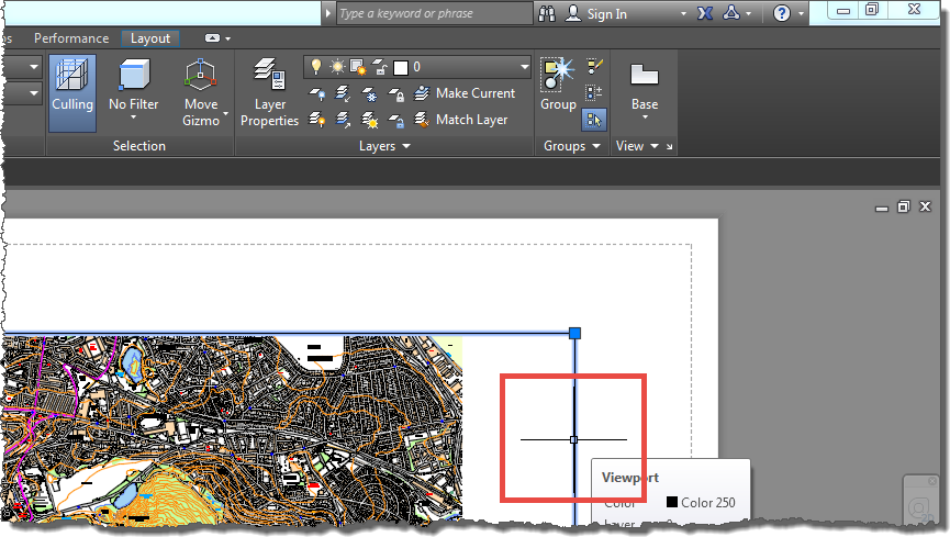
- This will get out you with a blank folio.
- Change the newspaper size to the ane you want to print. Exercise this past right clicking on the 'Layout1' tab and select 'Page Setup Managing director' from the popup menu.

- In the Page Setup Manager window select *Layout1* and and then 'Modify'.
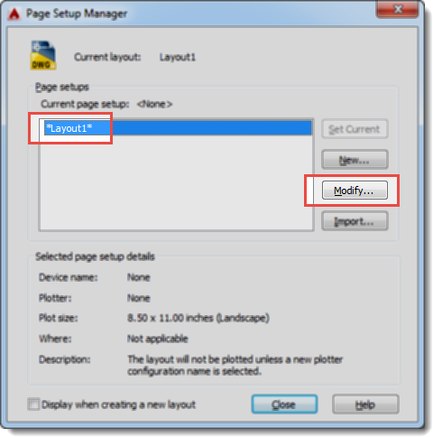
- Select the Printer and Paper Size, and check that the 'Plot calibration' units are set to 1:1:

- Select 'OK' and and then 'Close' on the Page Setup Manager window if it is still open up.
- Your sheet will now be set to whatever size you chose on the dialog above (we used A3).
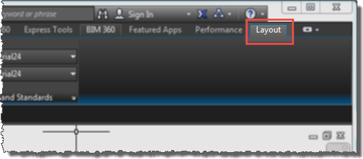
- Select the 'Layout' tab at the elevation of the command ribbon:
- In the 'Layout Viewports' department select 'Rectangular' to create a new viewport:

- To add a new Viewport to your page click once on the page in the top left hand corner inside the dotted line (the dotted line indicates the impress margin of your selected printer), move your mouse to the bottom right hand corner of the page and click again.
- You should now accept a full page Viewport with the map displayed:
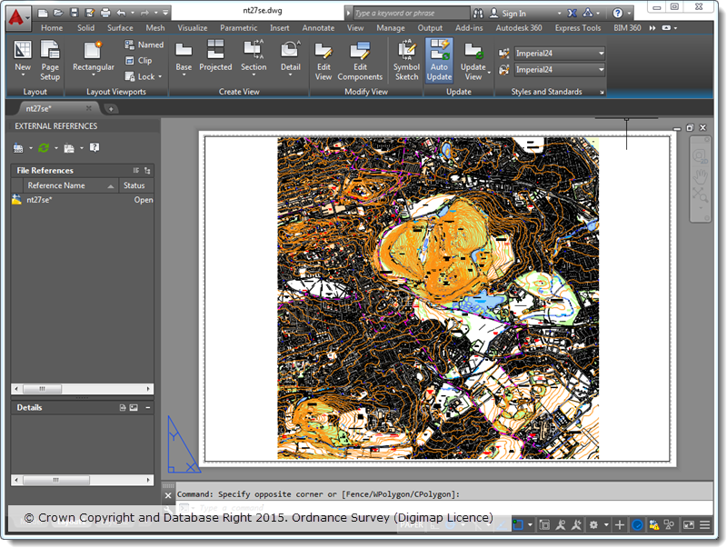
- Select the Viewport by clicking in one case on its edge so that it glows blue.
- The scale of the currently selected Viewport is displayed in a drop down in the lesser right corner:
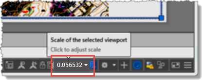
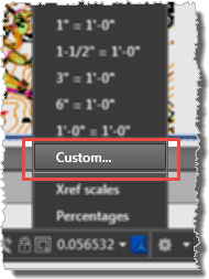
- Click on the dropdown arrow to aggrandize the list of scales and select 'Custom...' from the list:
- The currently available drawing scales are displayed:
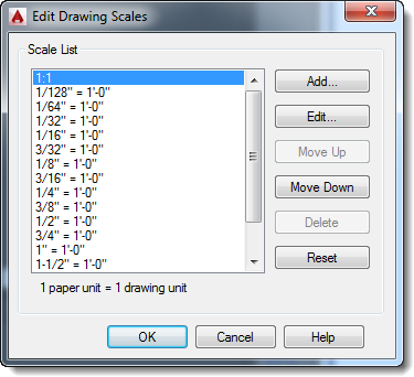
- Select 'Add...' to add together a new calibration, and complete as required. 'Paper units' are the units on the finished print out, 'Cartoon units' are the units within the AutoCAD model. So to add a custom scale to impress at 1:10,000 complete as shown below:
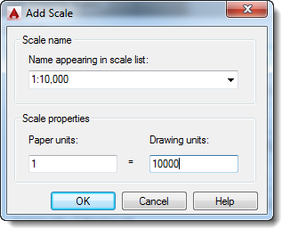
- Once completed, click 'OK' to close the window, and once again to close the 'Edit Cartoon Scales' window.
- Select the Viewport again then that it is highlighted in blueish.
-
The current drawing scale volition be displayed in the scale selection drib downwards:

-
Your new custom scale will be listed, select this and your drawing will now fill the Viewport at the selected calibration:
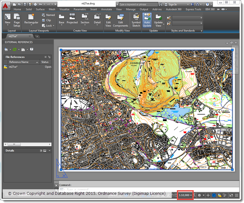
-
You can now print your map at the specified scale.
Source: https://digimap.edina.ac.uk/webhelp/digimapgis/autocad/standard_autocad_functions/printing_a_drawing_at_a_specific_scale_autocad.htm

0 Response to "How To Set Scale In Autocad Layout"
Post a Comment